ABOUT
Student Propelled Aerospace Rocket Kickstart I
SPARK I is a Sudent Researched And Developed (SRAD) resin 3D printred liquid rocket engine. SPARK I is UNLV's & Nevada's first ever student-led liquid rocket engine.
This engine features a single element swirl coaxial injector, fully resin printed. SPARK I uses ethanol and GOX in a one-to-one mixture ratio.
A 3D printed ablative liner is used for heat management.
Project manager: GAVIN CHUNG [SEDS UNLV VP]
email: seds@unlv.edu
Technical Advisor: Brandon Fallon
website: Brandonfallon.com
Sub-system leadership:
Electronics: Rabih Chaar,
Feed/Plumbing: Gavin Chung,
Test Stand: Foroutan Rezazadeh & Etsub Mechal,
Thrust Chamber Assembly: Ronaldo Valdivia & Gavin Chung
SIMULATION
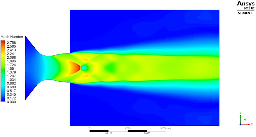
Thanks to our generous sponsor, ANSYS, we were able to run Computational Fluid Dynamics on our resin printed nozzle. Exhaustive simulations were performed to optimize the rocket engine performance. As shown, the exhaust velocity at the nozzle throat achieves sonic speeds. The infamous Mach diamonds make an appearance as the plume appears to be slightly under expanded.
ENGINE STATS
Propellants
GOX & Ethanol
ISP
209 seconds
Thrust
250 N
ANALYSIS
In this design, there are 5 main airframe components of interest. These include the nose cone, coupler, fins, bulkheads, avionics coupler. Each item underwent significant analysis to ensure structural integrity.
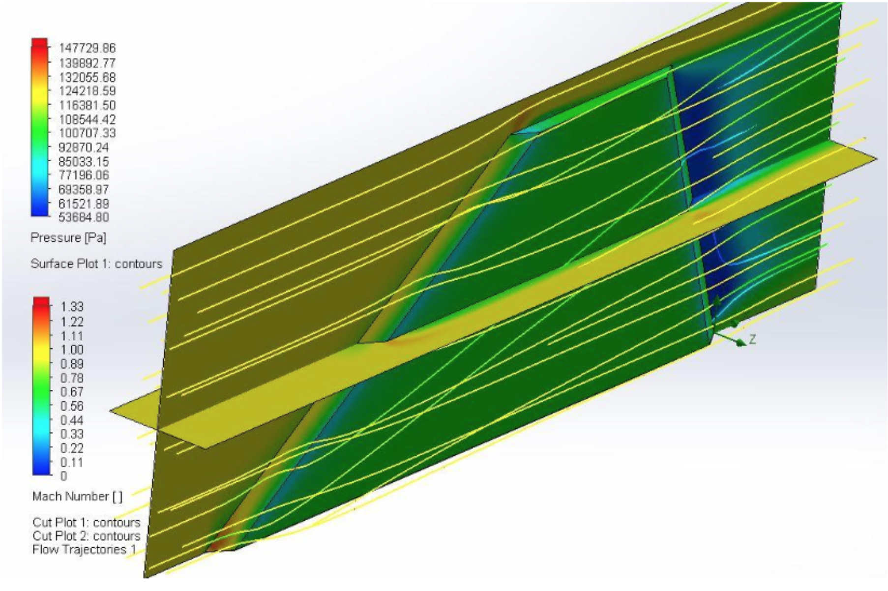
Fin Computational Fluid Dynamics
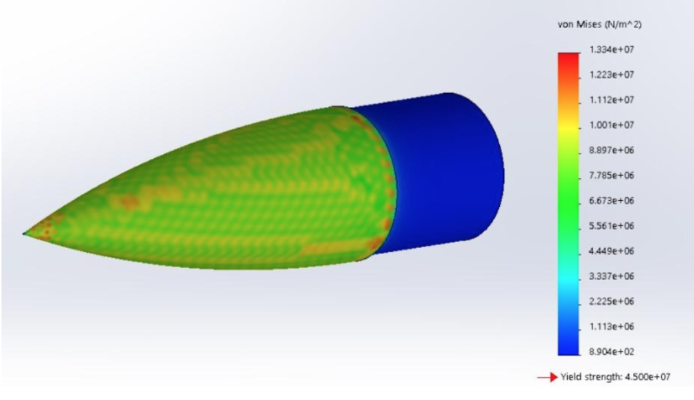
Von Mises Stress Analysis
Fiberglass Tube Compression Test
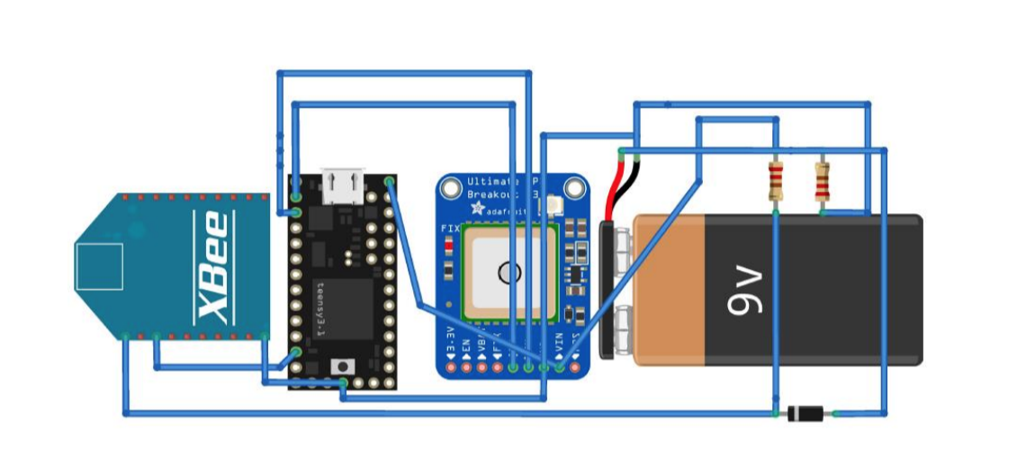
ELECTRONICS
The electronics for the Galactic Heaven Piercer include a tracker with radio, two event timers, a dual deployment
altimeter, and the standard competition altimeter, APRA, from PerfectFlite.
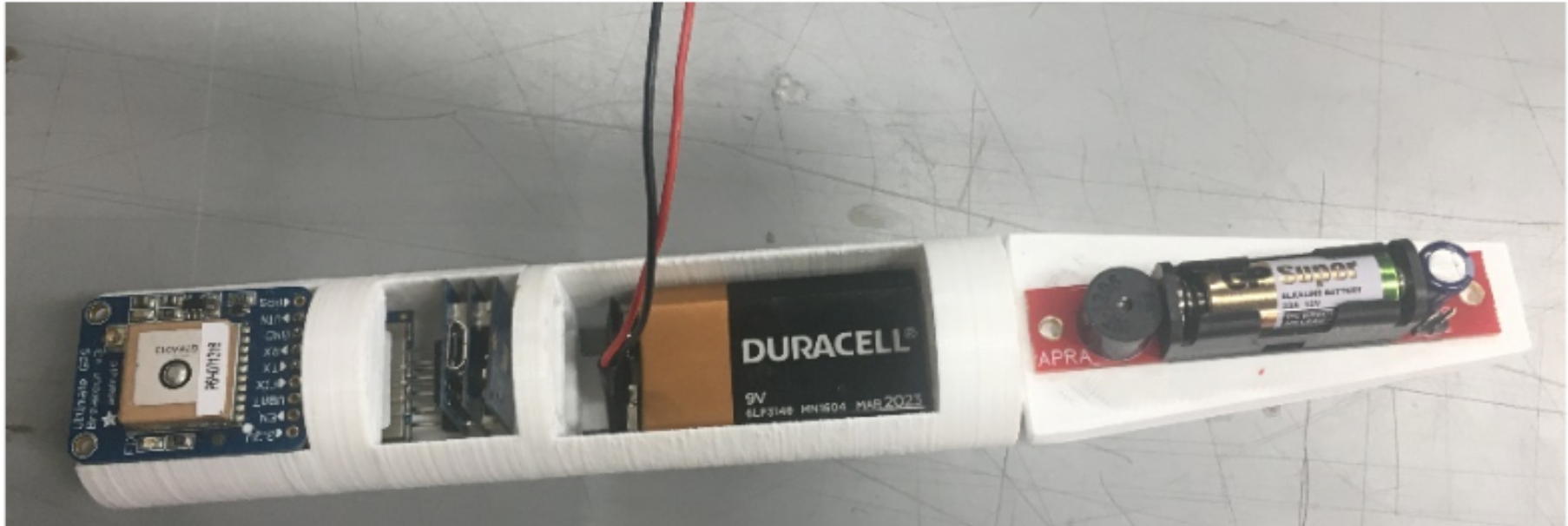
These electronics are housed in a 3D printed avionics holder, located inside a coupler in the upper portion of the rocket.
It will be in contact with the nose cone, allowing for up to 9 inches of electronics space.
Since a timed ejection is utilized, the electronics are placed above the motor, underneath a fiberglass bulkhead that will be epoxied in.
Wires run through this bulkhead to connect to igniters on the other side.
Two igniters are placed in the ejection caps, and third in the next motor to ensure ignition.
Image of Electronics Within Housing